Inverse Kinematic Arm | TGM Prototype
3-axis robotic arm with web-based inverse kinematic control
Project Overview
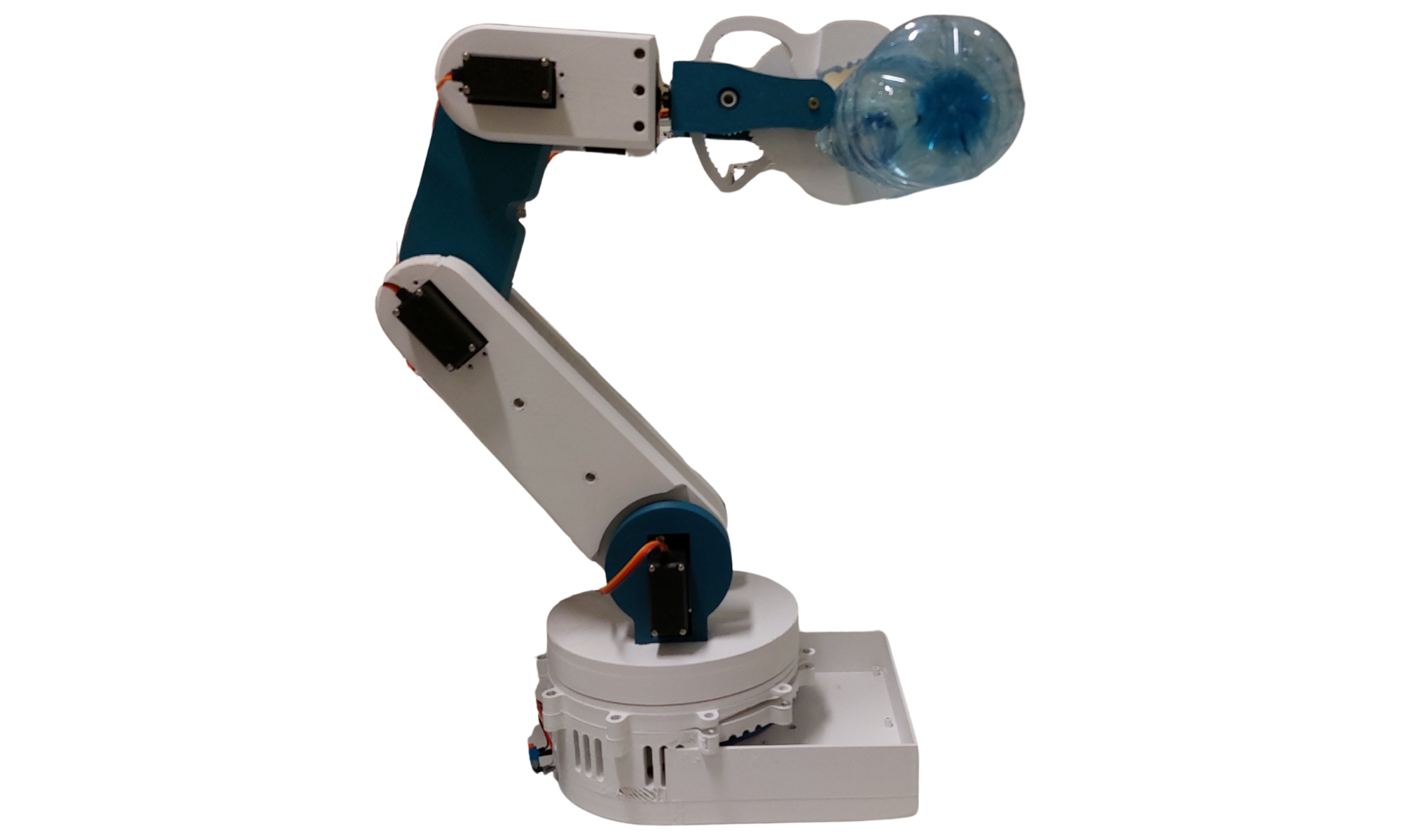
During my studies at TGM, I developed a 3-axis robotic arm prototype to explore the implementation of Inverse Kinematics (IK) in embedded systems.
The goal was to create a system where a user could interact with a modern web interface to define a target position, which the robot would then reach autonomously by calculating the required joint angles in real-time.
Realization
The project followed a full-stack approach, covering mechanical design, electronic integration, and software development.
Mechanical Design & Hardware
The robot’s structure was entirely designed for and produced via 3D printing. To handle the structural load while maintaining precision:
- Base Axis: Driven by a NEMA17 stepper motor to ensure high torque and stable rotation.
- Upper Axes: Controlled via PWM-driven servos, allowing for a lightweight yet responsive arm design.
- Control Unit: An ESP32 acted as the central controller, managing both the wireless communication and the pulse-width modulation for the actuators.
Software & Control Logic
The software architecture bridged a high-level frontend with low-level hardware execution:
- Web Interface: Built with Angular, providing a graphical “angular web interface” where users can select specific points or angles.
- Communication: The interface communicates with the ESP32 firmware via a network protocol, sending coordinate data for processing.
- Kinematic Engine: The firmware implements Inverse Kinematics, translating spatial coordinates into specific motor steps and PWM duty cycles for the servos.
Robotic Arm Controller Firmware
This documentation details the firmware logic for an ESP32-powered robotic arm. The system utilizes a hybrid actuation model, combining a high-torque stepper motor for the base with a PCA9685 PWM driver for the articulated arm segments and gripper.
Hardware Architecture
The controller is built to manage high-precision movements while maintaining a responsive web interface.
- Microcontroller: ESP32 (Dual-core enables simultaneous web handling and motor pulses).
- Base Actuation: NEMA Stepper motor via
DIR(GPIO 16) andSTEP(GPIO 17) pins. - Arm Segments: 6 Servos controlled via the PCA9685 16-channel PWM driver over I2C (Address
0x7F).
Networking & API Architecture
The ESP32 hosts a RESTful web server that accepts control commands via HTTP POST requests. This allows the arm to be controlled from any web browser or third-party application on the same network.
1. WiFi Connectivity
The device initializes a connection to the specified SSID. If the connection fails, the arm remains in a standby state until connectivity is established.
void connectToWiFi() {
  Serial.println("Connecting to WiFi...");
  WiFi.begin(ssid, pw);

  while (WiFi.status() != WL_CONNECTED) {
    delay(500);
    Serial.print(".");
  }
  Serial.print("\nConnected. IP: ");
  Serial.println(WiFi.localIP());
}
2. JSON Payload Specification
The arm’s position is updated by sending a JSON object to the /update endpoint. The values represent angles in degrees (0-180 for servos, 0-360 for the base).
{
  "base": 180,
  "segment1": 90,
  "segment2": 45,
  "segment3": 120,
  "gripperRotation": 90,
  "gripper": 30
}
3. Coordinate Mapping
Since the PCA9685 driver works with pulse-width units (typically 0-430 for standard servos) rather than degrees, the firmware maps incoming JSON values dynamically:
targetSegment1 = map(jsonDocument["segment1"], 0, 180, 0, 430);
targetGripper = map(jsonDocument["gripper"], 0, 180, 0, 430);
Motion Control & Easing Logic
To protect the mechanical components from high-inertia “jerks” and to reduce peak current draw, the firmware implements Incremental Smoothing (Easing).
Non-Blocking Update Loop
Instead of moving a servo immediately to the target, the loop() function increments the current position toward the target by one unit per cycle. This creates a smooth “chase” effect.
void loop() {
  server.handleClient(); // Handle incoming API calls

  // Incremental Base (Stepper) Movement
  if (base < targetBase) { base++; step(true); }
  else if (base > targetBase) { base--; step(false); }

  // Incremental Servo Easing
  // Updates segment positions step-by-step toward the target
  if (easingCounter % 4 == 0) {
    servoController.Servo(0, (segment1 < targetSegment1) ? segment1++ : (segment1 > targetSegment1) ? segment1-- : segment1);
  }

  // Final cycle delay regulates overall arm speed
  delay((float)armSpeed / 2.4f);
}
Stepper Pulse Generation
The stepper motor is driven manually via digital pulses. This ensures the base has maximum holding torque during static phases.
void step(bool direction) {
  digitalWrite(baseDirPin, direction);
  digitalWrite(baseStepPin, HIGH);
  delay(5);
  digitalWrite(baseStepPin, LOW);
  delay(5);
}
Technical Specifications
| Component | Interface | Values |
|---|---|---|
| Microcontroller | ESP32 | 240MHz / 512KB RAM |
| PWM Driver | PCA9685 | I2C (0x7F) |
| Stepper Driver | Digital Pulse | 10ms Pulse Cycle |
| JSON Buffer | ArduinoJson | 250 Bytes |
| Servo PWM Range | Internal | 0 - 430 Units |
Usage Notes
- Ensure the PCA9685 is powered by an external 5V/3A supply; the ESP32 cannot provide enough current for 6 servos.
- The
/updateendpoint is CORS-enabled, allowing for integration with browser-based JS dashboards. - The
armSpeedcan be adjusted via the/arm-speedendpoint to change the responsiveness of the easing logic.
Results
The prototype successfully demonstrated a seamless “Web-to-Motion” workflow.
By offloading the UI to a browser and the heavy lifting to the ESP32, the system achieved fluid motion sequences and proved the viability of using 3D-printed mechanics for educational robotic platforms. The integration of the NEMA17 stepper at the base provided the necessary stability to prevent oscillations during rapid coordinate shifts.
Technical Highlights
| Component | Description |
|---|---|
| Controller | ESP32 (Dual-core SoC) |
| Frontend | Angular Web Interface |
| Actuators | 1x NEMA17 Stepper, 2x PWM Servos |
| Mechanics | Fully 3D-printed chassis |
| Logic | Real-time Inverse Kinematics (IK) |
| Driver | Dedicated PWM/Stepper driver interface |
Skills & Competencies Gained
Developing this prototype allowed me to refine my skills in mechatronic system design and complex software-hardware interaction:
- Robotic Mathematics: Implementation of Inverse Kinematics to map Cartesian space to joint space.
- Full-Stack IoT Development: Connecting an Angular frontend to ESP32 firmware via wireless protocols.
- Mechanical Prototyping: Designing parts specifically for FDM 3D printing, considering tolerances and structural integrity.
- Hybrid Motor Control: Managing different actuation technologies (Steppers and Servos) within a single coordinated system.
- Embedded Firmware: Developing C/C++ code for the ESP32 to handle real-time signal processing and Wi-Fi stack management.
Reflection
This project was a pivotal experience during my TGM studies. It required more than just coding; it required a deep understanding of how geometry, mechanics, and software must align to turn a mathematical point on a screen into a physical movement in 3D space.